FLOW SWITCH 10/11/15/20

(Made in four versions depending on flow velocity)

  • FS 11 – 2× status output (depending on flow velocity)
  • FS 15 – 2× status output (1× depending on flow velocity and 1× on temperature)
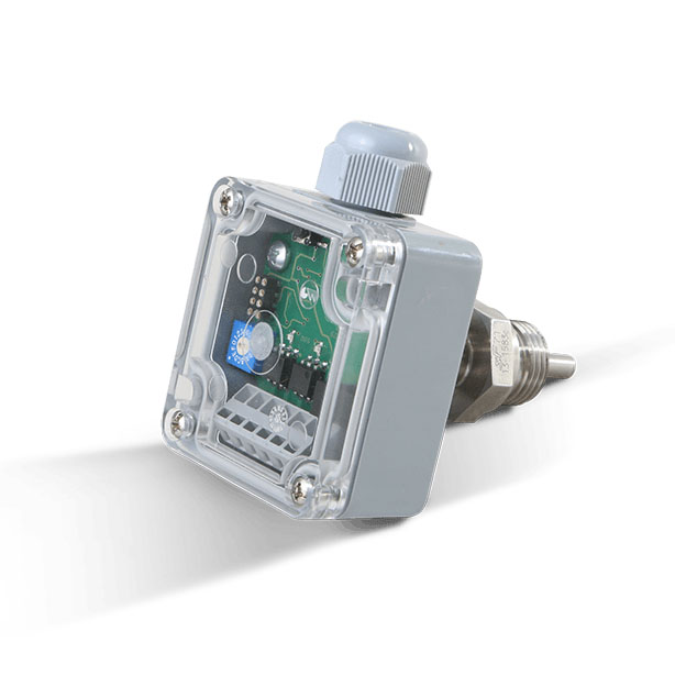
  • FS 20 – 1× status output and 1× current output (depending on flow velocity)

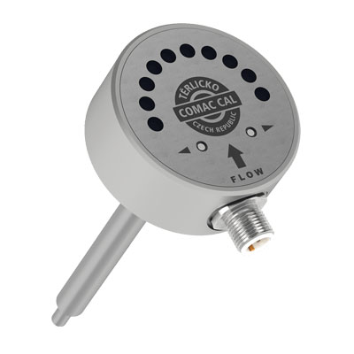
If the flow rate drops below the user specified limit, the status output will be changed. The flow rate is indicated by ten LEDs within the measurement range and you can select the boundary for making/breaking the contact in the same graduation. The measuring cycle takes from 4sec to 8sec with recommended measurement range 4 ÷ 150 cm/sec.

If the piping is empty, the sensor behaves identically as in the case of zero flow rate.

SENSOR CONTROLS

The flow switch contains two flush-buttons by which means it is possible to set

  • Switching point/points for flow velocity (or temperature in some case)
  • To change the logics of the making/breaking output
  • To calibrate minimum and maximum flow rate for the sensor
  • To reset default parameters from the manufacturer

ADAPTER BLOCK

If the flow rate of medium is to be monitored in a pipe smaller than DN25 (or the flow velocity is below the sensor range for the given pipe diameter), it is advantageous to use an adapter block with the corresponding flow velocity and thereby ensure proper functioning and maintain the installation conditions. The adapters are designed for the short version of 65mm sensor with the use of direct neck with G½“ pipe thread.

  Individual designs

  • FS adapter block DN20/G¾“ for 1 ÷ 10 l/min. (size 150×50×40 mm)
  • FS adapter block DN15/G½“ for 0.5 ÷ 5 l/min. (size 150×50×30 mm)
  • FS adapter block DN10/G¼“ for 0.2 ÷ 2 l/min. (size 150×50×30 mm)
  • FS adapter block DN4,7/G¼“ for 50 ÷ 500 ml/min. (size 70×50×30 mm)
  • FS adapter block DN2,7/G¼“ for 2 ÷ 100 ml/min. (size 70×50×30 mm)

Flow switch 10/11/15/20 main advantages

  • Possibility to use another status output (version FS 15) to monitor temperature according to setting
  • For FS 20 design, in addition to the making contact also 4 ÷ 20 mA current output
  • 10 LEDs to display the current flow and adjusted switching limits
  • „Self-teaching“ system with the possibility of Qmin and Qmax settings
  • Possibility to set switching limits (pre-set neutral zone)
  • Electrical connection through M12 (4-pin) connector
  • Continuous control of the sensor for correct operation
  • Full corrosion-proof construction

FLOW SWITCH 10/11/15/20 EX

It is a calorimetric flow switch so it is designed for monitoring of thermally conductive liquids. The big advantage of this type of flow switch is the fact that it is usable also in explosive atmosphere.

Key technical properties

Flow switch FS Ex 10/11/15/20 flow switch is certified for use in the following areas with explosive atmosphere:

I M1 Ex ia I Ma

II 1G Ex ia IIC T4..T6 Ga

II 1D Ex ia IIIC Txx°C Da

The flow switch for liquids is made in four versions. These are as follows:

FS 10Ex – 1× status output (depending on flow velocity)

FS 11Ex – 2× status output (depending on flow velocity)

FS 15Ex – 2× status output (1× depending on flow velocity and 1× on temperature)

FS 20Ex – 1× status output and 1× current output (depending on flow velocity)

The operational status is displayed using 10 LEDs. If the flow rate drops below the user specified limit (after exceeding in some case), the status output will be changed. The flow rate is indicated by ten LEDs within the measurement range and you can select the boundary for making/breaking the contact in the same graduation. The measuring cycle takes from 4sec to 8sec with recommended measurement range 4 ÷ 150 cm/sec (for default setting, the measurement range is 4 ÷ 400cm/sec). If the piping is empty, the sensor behaves identically as in the case of zero flow rate.

We offer two standard lengths of the bar type sensor according to piping ID at the installation site. The customer may select a bar type sensor 65 mm or 125 mm in length as needed. If the flow rate of medium is to be monitored in a pipe smaller than DN25 (or the flow velocity is below the sensor range for the given pipe diameter), it is advantageous to use an adapter block with the corresponding flow velocity and thereby ensure proper functioning and maintain the installation conditions. The adapters are designed for the short version of 65mm sensor with the use of direct neck with G½“ pipe thread. Individual designs of adapter blocks are as follows:

  • FS adapter block DN20/G3/4“ pro 5 ÷ 100 l/min. (rozměr 150×50×40 mm)
  • FS adapter block DN15/G1/2“ pro 2 ÷ 40 l/min. (rozměr 150×50×30 mm)
  • FS adapter block DN10/G1/4“ pro 0,4 ÷ 20 l/min. (rozměr 150×50×30 mm)
  • FS adapter block DN4,5/G1/4“ pro 0,1 ÷ 5 l/min. (rozměr 70×50×30 mm)
  • FS adapter block DN2,7/G1/4“ pro 0,075 ÷ 2 l/min. (rozměr 70×50×30 mm)

DISPLAYED SENSOR STATES

The designation of a switching point on the LED scale can be implemented in two colours (red and amber LEDs) that indicate simultaneously if the switching contact is closed or open:

In the case of FS15, the LED in the middle between the control buttons is used for temperature switching point indication. If the temperature of medium is above/below the set-point, the LED glows red and simultaneously indicates the open PIN2 (sensor delivered as a standard is set to be opened at a temperature above the set limit with the LED on).

When logics of the making/breaking points is changed by user, the logics of both outputs is changed at the same time (applies to versions FS 11 and FS 15).

FLOW SWITCH FS05

It is designed for flow rate monitoring of thermally conductive liquids. It is a simple flow velocity sensor with one or two switching contacts whereas each of them may have different flow velocity making/breaking points. Due to its construction, it is designed primarily as an OEM device used for substitution of mechanical flow switches in industrial processes.

Flow Switch FS05 key technical properties

The operational status is displayed using 6 LEDs. Identification of contact making is displayed by two LEDs. The making contact/contacts are set using a 16-position micro switch. Electrical connection is provided with WAGO cage clamps on the printed circuit board of the evaluation unit, namely by guiding through the cable gland with a very simple installation.

We offer two standard lengths of the bar type sensor according to piping ID at the installation site. The customer may select a bar type sensor 65 mm or 125 mm in length as needed.

Using the 16-state switch, the user sets the flow rate limit (or limits). As soon as the flow drops below the user-defined limit, the status output is changed as well. The measurement cycle time ranges from 4 to 8 sec. Flow velocity sensor measurement range is 4÷200 cm/sec. If the piping is empty, the sensor behaves identically as in the case of zero flow rate.

Application of the flow switch in industry

Thanks to absence of moving parts, it is an ideal substitution for mechanical flow switches with short service life. Conversely, flow velocity electrical evaluation is a guaranty of long time stability of all parameters. It is used with advantage, e.g. in cooling systems or building applications. Another possible employment is, e.g. in the technology complex where it provides information on operation of the entire technology, or conversely, as a safety element protecting against empty piping, low flow quantity, etc.

Flow Switch FS05 and its main advantages

  • Quick and easy installation
  • High reliability
  • Long service life
  • Indication of contact making using LEDs
  • Possibility of two switching positions
  • Continuous control of the sensor for correct operation
  • Sensor with a high IP rating
  • Utilization in various ID piping
  • Electrical connection using cable gland and WAGO clamp connectors
  • Low purchase costs thanks to simple construction (OEM product)
Generic selectors
Exact matches only
Search in title
Search in content
Post Type Selectors
product
Filter by Categories
Career
News