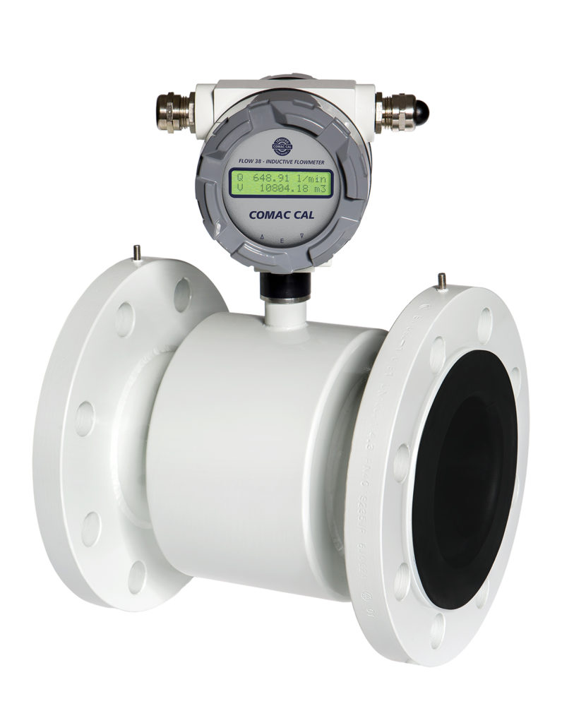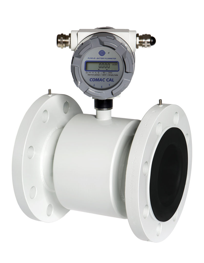


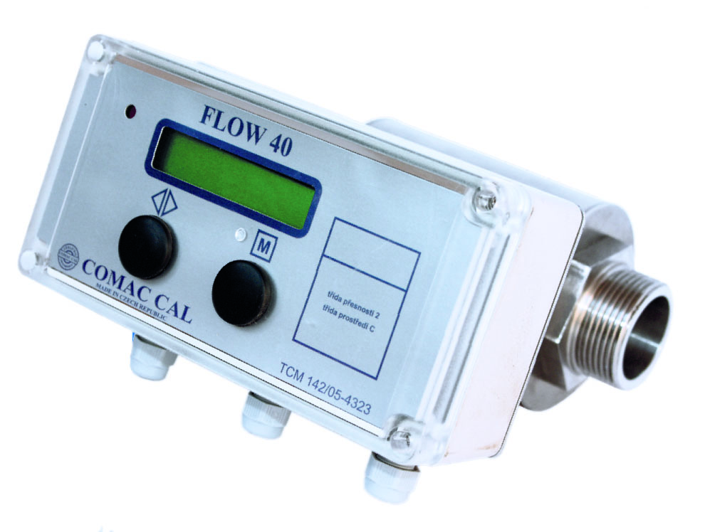
Inductive flow meter flow 40 serves, thanks to its certification, primarily for business measurement of the amount of liquids delivered. It is characterized by high operational reliability, accuracy and stability of metrological parameters.
Key technical parameters
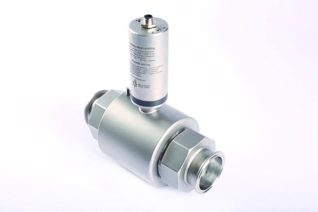
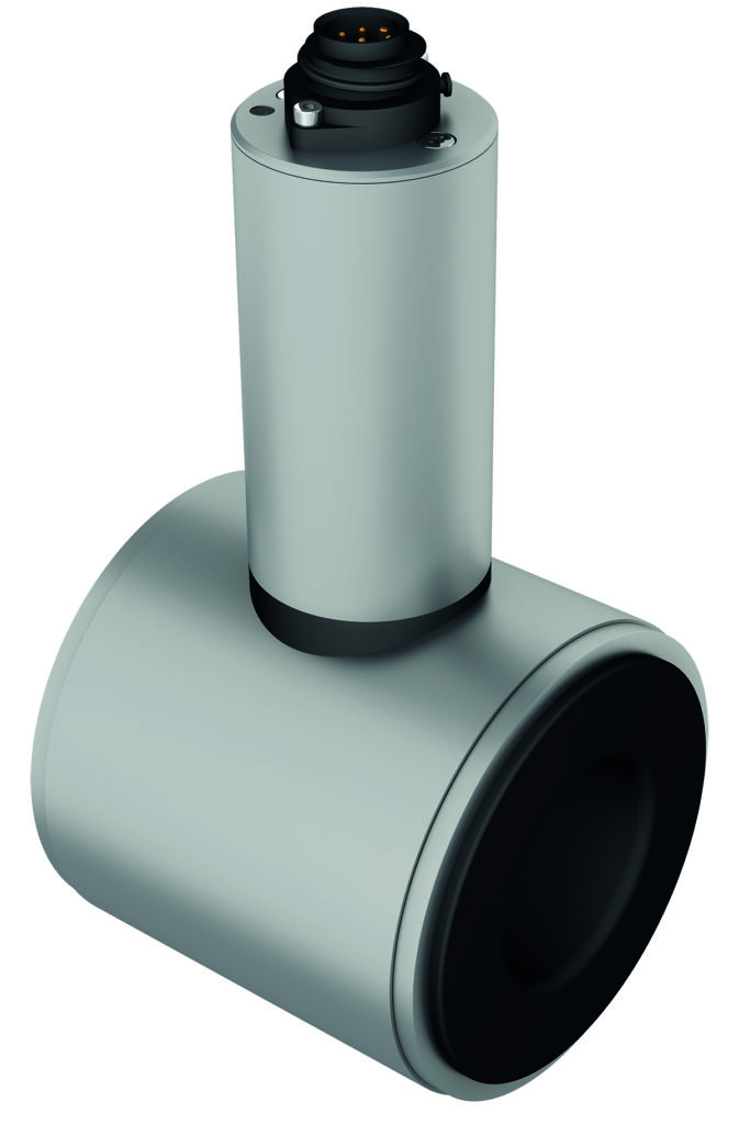
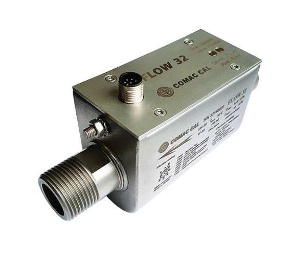
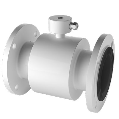
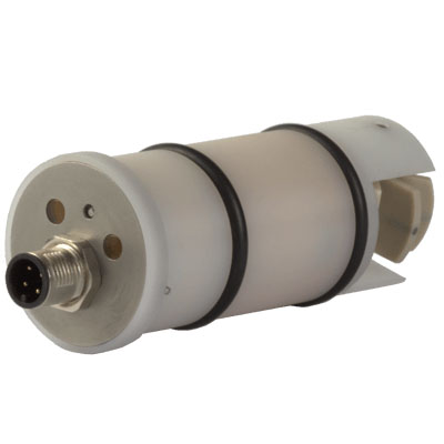
Standard versions can be made either in a compact or separate version.
Process connections are available, flanged, sandwich (flanged), threaded and then ductile fitting (DIN 11851) or clamp.
The flow meter also offers a wide range of outputs and communications for connection to various control systems. The customer has two pulse outputs (max. 400 Hz), current output 4 ÷ 20 mA for instantaneous flow monitoring or MBus or RS485 communication with M-BUS, AMSET, J & amp; C, C30 and others. Of course there is an extensive data archive. The two-line LCD display shows instantaneous flow, volume, return volume, date and time, monthly archive, daily archive, failure record, tariff value, and, in the event of a malfunction, its description. The meter also has two pulse inputs for external meters.
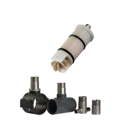
The flexibility of use is provided by several types of tabs, hard or soft rubber, rubber with a certificate for drinking water, PTFE, PFA or E-CTFE.
Application of the meter in industry
Inductive flow meter FLOW 40, thanks to its certification, is primarily used as a commercial gauge. It is used for use in the water industry eg in sewage treatment plants or in sewage networks as well as in industrial water distribution networks etc. It can also be used in the food and chemical industry for special media.
Inductive flow meter FLOW 40 and its main advantages
- certificate of commercial meter according to ČSN EN 1434
- high accuracy of measurement across the flow range
- long-term stability of metrological parameters
- simple and trouble-free operation and maintenance
- the flow sensor can be adapted to a very aggressive or alkaline fluid
- Does not contain moved parts
- high abrasion resistance
- does not cause pressure drops
- local and remote reading of all archived data in daily and monthly archives
- possibility to transfer data via GSM